Why MCE?
The MCE is the most comprehensive static electric motor test equipment available on the market today. Through a series of powerful diagnostic tests, the MCE provides a complete look at the health of an offline motor. The MCE provides critical information to technicians allowing them to diagnose problems early, thus reducing unwanted downtime.
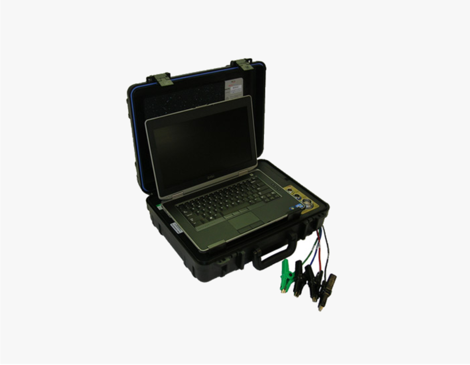
MCE Features
- Portable and battery powered
- Variable test voltage from 250 to 5000 volts
- Measures insulation resistance to 3 T Ohms
- Precision resistance measurement with resolution to 10 micro ohms using a 4-wire bridge test measurement
- And much more…
Fault Zone Analysis
Electric motors can be complex and difficult to diagnose and we understand this. That is why PdMA® Corporation utilizes the Six Fault Zone approach for analyzing electric motors. The MCE provides comprehensive data for each specific fault zone (Power Quality, Power Circuit, Insulation, Stator, Rotor, and Airgap), thus providing you with the knowledge to make key decisions regarding your electric motors.
Fault Zone – Power Circuit
The power circuit refers to all of the conductors and connections that exist from the point at which the testing starts through to the connections at the motor. It can include circuit breakers, fuses, contactors, overloads, disconnects, and lug connections. Research on industrial power distribution systems has shown that connectors and conductors are the source of 46% of the faults reducing motor efficiency.
The MCEMAX® powered by MCEGold® provides a unique advantage to test the power circuit and all the associated components. Many times a motor, although initially in perfect health, is installed into a faulty power circuit. This causes problems like voltage imbalances, current imbalances, sequence currents, etc. As these problems become more severe, the horsepower rating of the motor drops, causing temperatures to increase and insulation damage to occur. It is important to evaluate the resistance and inductance of a motor circuit once a motor is installed for service. High imbalances of voltage, current, resistance, or inductance could indicate problems with the motor or power circuit. Identifying minor imbalances early will eliminate catastrophic failures and headaches later.
Fault Zone – Insulation
The Insulation fault zone refers to the condition of the insulation between the windings and ground. For electrical equipment to operate properly and safely, it is important that the flow of electricity take place along well-defined paths or circuits and that it not be leaking from one path to another. Deterioration of the insulation systems can result in an unsafe situation for personnel exposed to the leakage current.
The MCE® technology allows you to identify potential problems with the insulation by recognizing adverse trends in resistance to ground. After conducting a baseline test, all subsequent tests are compared to the initial data with significant changes in value highlighted in yellow for caution or red for alarm.
Fault Zone – Stator
The stator fault zone is often considered one of the most controversial fault zones due to the significant challenge of early fault detection and the prevention of motor failure surrounding the stator windings. Stator windings are the heart of the motor, producing the rotating magnetic field, induction current, and torque to turn the rotor and shaft. This challenge is further intensified in higher voltage machines, where the fault-to-failure time frame becomes much shorter. The stator fault zone is identified as the health and quality of the insulation between the turns, coils, and phases within the slots and end turns of the electric motor.
Turn-to-turn or phase-to-phase shorts can be catastrophic to the motor and not necessarily be detected by the standard megohmeter. Excessive inductive imbalance, resistive imbalance, vibration, partial discharge, or poor insulation quality can lead to stator failure and should be monitored regularly to prevent a shortened life of the electric motor stator. Stator analysis using EMAX technology is performed by evaluating the phase relationship of voltage and current for each of the three phases of an AC induction motor.
Fault Zone – Rotor
Rotor health refers to the integrity of the rotor bars, rotor laminations, and end rings of the squirrel cage induction motors. In a joint study by EPRI and General Electric, rotor defects were estimated to be responsible for approximately 10% of the motor failures. The rotor, although responsible for only a small percentage of the motor problems, can influence other fault zones to fail.
MCE® motor circuit analysis uses inductance measurements taken from each phase of the stator windings and compares them at different rotor positions to further define the condition of the rotor. Advanced systems like
EMAX provide simultaneous analysis of all three phases in its current signature analysis, which is an advantage over analyzing a single current. Using inductance measurements, current analysis, and other rotor testing technology provides the user with the ability to see very early changes in the magnetic signature of the rotor.
Fault Zone – Air Gap
The Air Gap fault zone describes the measurable distance between the rotor and stator within the motor. If this distance is not equal throughout the entire circumference air gap eccentricity occurs. The varying magnetic flux within the air gap creates imbalances in the current flow, which can be identified in the current spectrum.
Eccentricity analysis using the MCE® Rotor Influence Check (RIC) test is most successfully applied in troubleshooting if pre-existing data is available so that trends can be observed. Eccentricity analysis using EMAX technology is performed through a high frequency spectrum of the current signal. If the number of rotor bars and the speed are known, the MCEGold® software automatically places an (X) at the four peak locations which identify eccentricity.